Masonry Fireplace CAD Details: A Comprehensive Overview
Masonry fireplaces, known for their aesthetic appeal and efficient heating capabilities, remain a popular architectural feature in residential and commercial buildings. The design and construction of a masonry fireplace require precise planning and execution, often leveraging Computer-Aided Design (CAD) software to ensure accuracy and compliance with building codes. CAD details provide a visual representation of the fireplace's components, dimensions, and construction methodology, enabling architects, engineers, and contractors to collaborate effectively and minimize errors throughout the building process.
This article aims to provide a comprehensive overview of masonry fireplace CAD details, covering essential aspects such as component representation, standard symbols, critical dimensions, and integration with overall building plans. Understanding the nuances of these details is crucial for ensuring the safe and efficient operation of a masonry fireplace while adhering to relevant regulations and industry best practices.
Essential Components Depicted in CAD Details
A comprehensive masonry fireplace CAD detail should accurately represent all vital components, providing a clear understanding of their individual functions and their relationship within the overall structure. These components are often represented using specific symbols and abbreviations for clarity and consistency across different design documents.
The
firebox
, the chamber where combustion occurs, is a critical element. The CAD detail will typically illustrate the firebox's dimensions, construction materials (typically firebrick), and the angle of the firebox walls, which influences heat radiation. Internal dimensions are particularly crucial for proper draft and combustion efficiency. The firebox opening, including height and width, should also be shown, as these are factors in smoke management.The
smoke chamber
, located above the firebox, funnels smoke and combustion gases into the flue. Its design significantly affects draft and smoke dilution. CAD details illustrate the smoke chamber's shape, which is typically either corbelled or sloping, and its dimensions. The transition between the firebox and smoke chamber needs to be precisely detailed to prevent turbulence and backdrafting.The
flue
, a vertical passage within the chimney, carries smoke and gases away from the fireplace. The CAD detail will specify the flue's diameter or cross-sectional area, material (e.g., clay flue liner, stainless steel), and height. Flue size is critical for proper draft and preventing the buildup of creosote, a flammable byproduct of combustion. Details regarding flue liner installation, including mortar joints and support systems, are also provided.The
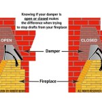
damper
, a movable plate within the flue, controls airflow. CAD details should specify the type of damper (e.g., throat damper, top-sealing damper), its dimensions, and its operating mechanism. A properly functioning damper is essential for preventing heat loss when the fireplace is not in use and for controlling draft during operation.The
hearth
, the non-combustible area in front of the fireplace opening, protects the floor from sparks and embers. The CAD detail will specify the hearth's dimensions, material (e.g., brick, stone, concrete), and thickness. Building codes dictate minimum hearth dimensions based on the size of the firebox opening.The
chimney
, the exterior structure that contains the flue, provides structural support and weather protection. The CAD detail will illustrate the chimney's overall height, cross-sectional dimensions, and construction materials (e.g., brick, stone, concrete block). Details regarding chimney flashing, which prevents water penetration at the roof line, are also included. The crown, a protective cap at the top of the chimney, is also detailed to ensure proper water runoff and prevent deterioration of the chimney structure.The
ash dump
orash pit
, is often incorporated into masonry fireplace designs. It is a contained area beneath the firebox floor where ash can be conveniently collected and removed. The CAD details would illustrate the size, shape, and location of the ash dump, its access door, and its construction materials.Standard Symbols and Abbreviations
Consistent use of standard symbols and abbreviations is essential for clear communication within CAD details. These conventions minimize ambiguity and enable different stakeholders to interpret the drawings accurately. Organizations like the American Institute of Architects (AIA) and industry-specific groups often publish recommended standards, but local building codes can also influence the symbolism used.
For instance, firebrick is typically represented with a specific hatch pattern that differs from standard brick. Concrete block is shown with a different hatch pattern, indicating its material composition. Insulation materials, such as mineral wool or ceramic fiber blankets, are also designated with distinct symbols. These variations allow for easy identification of different materials within the fireplace construction.
Abbreviations are commonly used to denote materials, dimensions, and other relevant information. For example, "CL" might represent the centerline, "O.C." signifies "on center," and specific abbreviations are used to denote different types of brick, mortar, and insulation materials. A key or legend should always accompany the CAD detail to clarify the meaning of each symbol and abbreviation used.
Dimension lines are also standardized to indicate the precise measurements of each component. These lines typically include arrowheads at each end, extension lines extending from the object being measured, and a numerical value indicating the dimension. Tolerances, the permissible variation in dimensions, may also be specified in the CAD detail to ensure proper fit and function of the fireplace components.
Critical Dimensions and Design Considerations
Accurate dimensions are paramount in CAD details to ensure proper construction and functionality of the masonry fireplace. These dimensions are not only essential for accurate material ordering but also for compliance with building codes and safety regulations.
The firebox opening dimensions, including height and width, must adhere to specific requirements for smoke management and combustion efficiency. An improperly sized opening can lead to smoke spillage into the room. The depth of the firebox is also a critical dimension, influencing the amount of fuel that can be burned and the heat output of the fireplace.
Flue dimensions, including diameter or cross-sectional area and height, are crucial for proper draft. Under-sized flues can result in poor draft and smoke backflow, while oversized flues can lead to excessive heat loss. The flue's height must also be sufficient to create adequate draft, typically extending at least two feet above the highest point of the roof within a ten-foot radius.
Hearth dimensions are dictated by building codes to protect combustible materials from sparks and embers. The hearth must extend a minimum distance in front of the firebox opening and to the sides, depending on the size of the opening. The hearth material must also be non-combustible and capable of withstanding high temperatures.
Chimney height and location are influenced by building codes and prevailing wind conditions. The chimney must extend beyond any nearby obstructions, such as trees or adjacent buildings, to ensure proper draft. The chimney's structural integrity must also be addressed, particularly in areas prone to seismic activity or high winds. Reinforcement details, such as steel rebar within the chimney, should be clearly indicated in the CAD detail.
In addition to dimensions, other design considerations that should be reflected in the CAD details include the fire resistance rating of the fireplace walls, the type of mortar used, and the detailing of expansion joints to accommodate thermal movement. Proper detailing of these aspects is crucial for ensuring the long-term durability and safety of the masonry fireplace.
The CAD detail should also indicate the proposed location of any required cleanout doors for the flue and ash pit. These cleanout doors provide access for maintenance and removal of accumulated ash and debris, which is essential for maintaining proper fireplace operation and preventing fire hazards.
Proper CAD details will incorporate notes which direct the contractor as to the materials to be used, the proper installation methods, and all minimum clearances. These notes are an essential communication tool.
CAD details will also often show integration of the fireplace with adjacent building elements, such as framing and roofing materials. This comprehensive approach maximizes compatibility and ensures proper integration of the fireplace into the overall building design.

Masonry Fireplaces Firerock Caddetails

Get 20 Cad Drawings For Designing The Ideal Fireplace Your Project Design Ideas Built World

Fireplace Detail Plan And Section 2d View Cad Structural Block Layout File In Dwg Format Detailed Plans Brick

20 Cad Drawings Of Fireplaces To Keep You Cozy Design Ideas For The Built World

01 Fireplace Detail International Masonry Institute Brick Indoor

Brick Fireplace Plan Layout File Cadbull

Fireplace Details Cad Files Dwg Plans And

Technical Drawing Masonry Fireplace Chimney Design Dimensions
Chimney Detail Cad Design Free Blocks Drawings Details

Fire Place Detail 2d View Elevation And Section Cad Block Layout Autocad File Cadbull
Related Posts