Gas Fireplace Thermopile Testing: Ensuring Safe and Efficient Operation
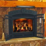
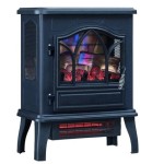
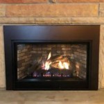
A gas fireplace offers a convenient and aesthetically pleasing heating solution for many homes. Unlike traditional wood-burning fireplaces, gas fireplaces provide instant warmth with minimal effort and cleanup. However, the reliable operation of a gas fireplace relies heavily on the proper functioning of its safety components, one of the most critical being the thermopile. A failing thermopile can lead to inconsistent operation, pilot light outages, and ultimately, a non-functional fireplace. Therefore, understanding how to test a thermopile is essential for homeowners and technicians alike to ensure safe and efficient operation.
The thermopile is a thermoelectric generator composed of multiple thermocouples connected in series. Its primary function is to generate sufficient millivoltage to power the gas valve, enabling the main burner to ignite. The pilot light constantly heats the thermopile, creating a temperature difference between the hot and cold junctions of the thermocouples. This temperature differential induces a voltage according to the Seebeck effect. This voltage, though small, is enough to hold the gas valve open, allowing gas to flow to the main burner when the fireplace is ignited. Without a properly functioning thermopile, the gas valve will close, shutting off the gas supply and preventing the main burner from operating.
Regular testing of the thermopile is crucial for maintaining the fireplace's reliability. Factors such as age, exposure to contaminants, and overheating can degrade the performance of the thermopile over time. Early detection of a faulty thermopile allows for timely replacement, preventing potential safety hazards and ensuring consistent heating performance during the colder months. This article will detail the steps involved in testing a gas fireplace thermopile, providing a comprehensive guide to troubleshoot and diagnose potential issues.
Understanding the Thermopile Circuit: Key Components and Their Roles
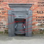
Before delving into the testing procedure, it is important to understand the components associated with the thermopile circuit. These components work together to ensure that the gas fireplace operates safely and efficiently. A typical thermopile circuit includes the pilot assembly, the thermopile itself, the gas valve (specifically the millivolt valve), and sometimes a safety switch or sensor. Each component plays a vital role in the overall operation of the fireplace.
The pilot assembly houses the pilot light, which provides the constant source of heat to the thermopile. The pilot light is typically a small, steady flame that burns continuously. It's critical to ensure the pilot flame is properly positioned to impinge directly on the thermopile. A weak or misdirected pilot flame will not adequately heat the thermopile, resulting in insufficient voltage generation.
The thermopile, as previously described, converts heat energy into electrical energy. It is typically located near the pilot assembly to maximize its exposure to the pilot flame. The thermopile has two wires that connect to the gas valve, transmitting the generated millivoltage.
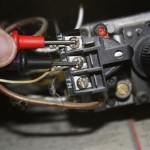
The gas valve, specifically a millivolt valve in this context, is an electromagnetically operated valve that controls the flow of gas to the main burner. It is designed to open only when sufficient millivoltage is provided by the thermopile, ensuring that the main burner can only ignite when the safety circuits are functioning correctly. This valve typically has terminals for connecting the thermopile wires, as well as terminals for connecting a thermostat or switch to control the fireplace operation.
Additional safety components, such as flame rollout sensors or overheat sensors, may be incorporated into the circuit. These sensors are designed to shut off the gas supply if abnormal conditions are detected, such as a flame extending beyond the fireplace or excessive temperatures within the firebox. These sensors are typically wired in series with the thermopile circuit, interrupting the voltage supply to the gas valve if triggered.
A proper understanding of these components and their roles is crucial for effective troubleshooting. Identifying a malfunctioning component within the thermopile circuit is the first step toward diagnosing the root cause of a fireplace issue.
Step-by-Step Guide to Testing a Gas Fireplace Thermopile
Testing a gas fireplace thermopile requires a multimeter capable of measuring millivolts DC (mVDC). The testing procedure involves measuring both the open circuit voltage and the closed circuit voltage of the thermopile. The open circuit voltage represents the voltage generated when the thermopile is not connected to the gas valve, while the closed circuit voltage represents the voltage generated when the thermopile is connected to the gas valve and powering the system.
Before commencing any testing, it is imperative to ensure the gas supply to the fireplace is shut off. This prevents accidental gas leakage during the testing process. Locate the gas shut-off valve, typically located upstream of the fireplace, and turn it to the "off" position. Allow the fireplace to cool down completely before proceeding.
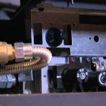
Next, locate the thermopile and its connection to the gas valve. It is usually a small cylindrical component with two wires connected to the gas valve terminals. Disconnect both wires from the gas valve terminals. Ensure the wires are properly insulated to avoid short circuits during the testing process.
Set the multimeter to the millivolts DC (mVDC) range. Connect the multimeter probes to the thermopile wires. Ensure proper polarity: the positive probe to the positive wire and the negative probe to the negative wire. Light the pilot light according to the manufacturer's instructions. Allow the pilot light to heat the thermopile for a few minutes, typically around two to three minutes, to allow the thermopile to reach its operating temperature.
Observe the multimeter reading. This reading represents the open circuit voltage of the thermopile. A healthy thermopile should typically generate an open circuit voltage of at least 650-750 mVDC. Refer to the manufacturer's specifications for the specific voltage range expected for your particular thermopile model. If the open circuit voltage is significantly lower than the specification, the thermopile is likely faulty and requires replacement.
After measuring the open circuit voltage, it is crucial to measure the closed circuit voltage, also known as the "under load" voltage. This test assesses the thermopile's ability to maintain sufficient voltage while powering the gas valve. Reconnect the thermopile wires to the gas valve terminals. Ensure the connections are secure and properly tightened.
With the thermopile connected to the gas valve, relight the pilot light and allow the thermopile to heat up for a few minutes. Place the multimeter probes on the thermopile wires where they connect to the gas valve terminals. Note the voltage reading displayed on the multimeter. This is the closed circuit voltage.
A healthy thermopile should maintain a closed circuit voltage of at least 325-350 mVDC. Again, consult the manufacturer's specifications for your particular thermopile model. If the closed circuit voltage drops significantly below this threshold, even if the open circuit voltage was within range, it indicates that the thermopile is unable to provide sufficient power to the gas valve under load. This can be caused by internal resistance within the thermopile or a weak pilot flame failing to provide adequate heat.
If the closed circuit voltage is low, verify the pilot flame's impingement on the thermopile. Ensure the flame is properly aligned and engulfing the thermopile tip. Check for any obstructions that might be blocking the heat from reaching the thermopile. Adjust the pilot flame if necessary, following the manufacturer's instructions. If the closed circuit voltage remains low after adjusting the pilot flame, the thermopile is likely faulty and requires replacement.
Interpreting Thermopile Test Results and Troubleshooting Common Issues
The results obtained from the thermopile testing procedure provide valuable insights into the condition of the thermopile and the overall health of the fireplace's safety circuit. By carefully analyzing the open circuit voltage and closed circuit voltage readings, one can effectively diagnose potential issues and determine the appropriate course of action.
An open circuit voltage that falls significantly below the manufacturer's specified range is a clear indication of a faulty thermopile. This suggests that the thermocouples within the thermopile have degraded, resulting in reduced voltage generation. In such cases, replacing the thermopile is the most appropriate solution.
A normal open circuit voltage but a low closed circuit voltage indicates that the thermopile is generating sufficient voltage when unloaded but struggles to maintain voltage when connected to the gas valve. This can be caused by several factors. One possibility is a weak pilot flame, which fails to provide adequate heat to the thermopile. Adjusting the pilot flame or cleaning the pilot assembly may resolve this issue. Another possibility is excessive resistance within the thermopile itself, hindering its ability to deliver sufficient current. In this case, thermopile replacement is recommended.
Additionally, a low closed circuit voltage can be caused by a malfunctioning gas valve. If the gas valve has internal resistance or a weak solenoid, it may require more voltage than a healthy thermopile can provide. To diagnose this, one can bypass the thermopile with a correctly sized DC power supply to attempt to activate the valve. However, proceed with extreme caution as this bypasses critical safety features. If the gas valve fails to activate even with the external power supply, it is likely faulty and needs replacement.
If the open circuit voltage is extremely low or zero, there could also be a break in the thermopile wires. Carefully inspect the wires for any signs of damage, such as cuts, frayed insulation, or loose connections. Repair or replace the wires as needed. If the wires are intact, the thermopile itself is likely the culprit.
Before replacing the thermopile, inspect the surrounding components for any signs of damage or corrosion. Clean the pilot assembly and thermopile mounting area to ensure proper heat transfer. Consider replacing the pilot assembly along with the thermopile to ensure optimal performance and longevity.
After replacing the thermopile, always retest the system to verify proper operation. Measure both the open circuit voltage and closed circuit voltage to ensure they are within the manufacturer's specifications. Observe the fireplace operation for several minutes to confirm that the main burner ignites reliably and the pilot light remains lit. Should any issues persist, consult the manufacturer's service manual or contact a qualified gas fireplace technician for further assistance.

How To Test Your Thermopile Www Mygasfireplacerepair Com

How To Test Your Thermopile Www Mygasfireplacerepair Com

Fireplace How To Testing A Thermopile

Identifying Gas Fireplace Parts Www Mygasfireplacerepair Com

How To Test Your Thermopile Www Mygasfireplacerepair Com

How To Test Your Thermopile Www Mygasfireplacerepair Com

Gas Fireplace Won T Stay Lit Magic Touch Mechanical

Diy Gas Fireplace Won T Light How To Clean Your Thermopile And Thermocouple

Fireplace How To Testing The Switch Circuit In A Millivolt System

Fireplace How To Testing A Thermocouple
Related Posts